| OUTPUT |
| Output Voltage | 24V | 36V | 48V |
| Load Current Range | 0 ~ 20A | 0 ~ 13.3A | 0 ~ 10A |
| Battery Charging Current | 15.4A | 10.2A | 7.7A |
| Recommended Battery Capacity | 20 ~ 200AH | 13.3 ~ 133AH | 10 ~ 100AH |
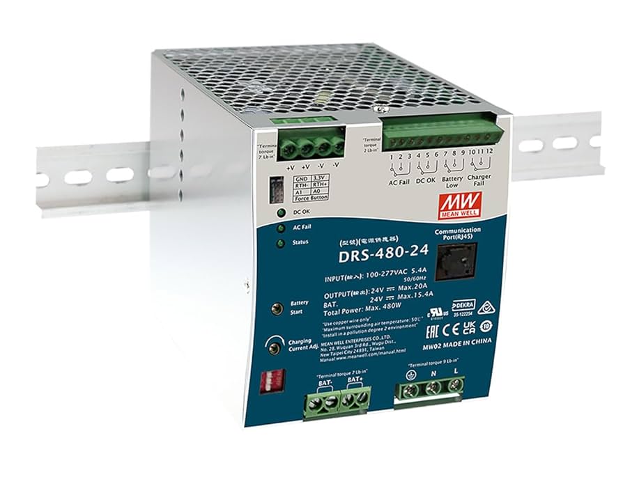
| Total Output Power (max.) | Combined power on all Channels must not exceed 480W, load has priority. 550W peak capability within 5s. |
| Ripple & Noise (max.) | 240mVp-p | 360mVp-p | 480mVp-p |
| Voltage Adjustment Range | 20.9~29.1V | 31.3~43.7V | 41.8~58.2V |
| Voltage Tolerance | ±1.0% |
| Line Regulation | ±0.5% |
| Load Regulation | ±0.5% |
| Setup, Rise Time | 2400ms, 1000ms / 230VAC; 2400ms, 1000ms / 115VAC at full load |
| Hold up Time (typ.) | 16ms / 230VAC, 10ms / 115VAC at full load |
| INPUT |
| Voltage Range | 90 ~ 305VAC, 127 ~ 431VDC |
| Frequency Range | 47 ~ 63Hz |
| Power Factor (typ.) | PF > 0.95/230VAC, PF > 0.98/115VAC at full load |
| Efficiency (typ.) | 92.5% | 93.5% | 93.5% |
| AC Current (typ.) | 2.8A / 115VAC, 1.4A / 230VAC |
| Inrush Current (typ.) | Cold start: 30A / 115VAC, 60A / 230VAC |
| Short Circuit | Protection type: Constant current limiting, power will shutdown after 5s, re-power on to recover |
| PROTECTION |
| Overload | 105 ~ 135% rated output power |
| Over Voltage | Shut down output voltage, re-power on to recover |
| Over Temperature | Shut down output voltage, recovers automatically after temperature goes down |
| Battery Cut Off | 20.9±0.5V | 31.3±0.7V | 41.8±1V |
| Reverse Polarity | Internal MOSFET, no damage after battery polarity reversed |
| FUNCTION |
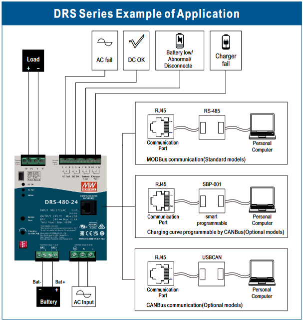
| AC Fail | Relay contact output, ON: AC OK; OFF: AC Fail; max. rating: 30VDC/1A |
| DC OK | Relay contact output, ON: DC OK; OFF: DC Fail; max. rating: 30VDC/1A |
| Battery Low | Relay contact output, ON: Battery OK; OFF: Battery Low; max. rating: 30VDC/1A |
| Charger Fail | Relay contact output, ON: Charger OK; OFF: Charger Fail; max. rating: 30VDC/1A |
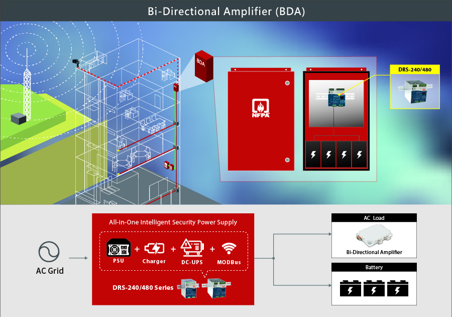
| Battery Start | System directly start from battery and does not require AC power |
| DC-UPS | UPS switch to battery power within 10ms of AC failure |
| Adjustable Charge Current | 20% ~ 100% charging current adjustable by VR |
| Battery Temperature Compensation | The system can change battery charging voltage by detecting battery temperature |
| ENVIRONMENT |
| Working Temp. | -30 ~ +70°C (Refer to "Derating Curve") |
| Storage Temp., Humidity | -40 ~ +85°C, 10 ~ 95% RH non-condensing |
| Temp. Coefficient | ±0.03%/°C (0~50°C) |
| Vibration | 10 ~ 500Hz, 5G 10min/cycle, 60min each along X, Y, Z axes |
| Operating Altitude | 2000 meters (OVC III) |
| Over Voltage Category | According to BS EN/EN61558-1:2018 clause 10.2 at 2000 meters |
| SAFETY & EMC |
| Safety Standards | UL62368-1, BS EN/EN62368-1, RCM AS/NZS 62368.1, EAC TP TC 004 approved |
| Isolation Resistance | I/P-O/P: 100M Ohms / 500VDC / 25°C / 70% RH |
| EMC Emission | BS EN/EN55032 (CISPR32) Class B, BS EN/EN55024 |
| EMC Immunity | BS EN/EN61000-4-2/3/4/5/6/8/11, Level 3/4, Criteria A |
| Fire Alarm System | Compliance to BS EN54-4 |
| OTHERS |
| MTBF | Telcordia: 556.6K hrs; MIL-HDBK-217F: 74.5K hrs (25°C) |
| Dimension (W x H x D) | 110 x 125.2 x 150.7 mm |
| Packing | 1.65kg; 12pcs/22.1kg/1.08CUFT |
| NOTE | 1. All parameters NOT specially mentioned are measured at 230VAC input, rated load and 25°C ambient temperature.
2. Ripple & noise are measured at 20MHz bandwidth by using a 12" twisted pair-wire terminated with a 0.1µF and 47µF parallel capacitor.
3. Tolerance includes setup tolerance, line regulation, and load regulation.
4. Derating may be needed under low input voltage. Please check the derating curve for details.
5. Battery low cut-off voltage detection may vary with the condition and aging of the battery.
6. Installation clearance: 40mm on top, 20mm at bottom, 5mm left and right side; 15cm recommended when adjacent to heat sources. |